


We use cookies
This site uses cookies to provide you with a great user experience. You can view our cookies policy here.
Our Group
Specializing in innovative technologies, products, and solutions, our companies have served the satellite ground network industry for 30 years and counting.
Our Markets
Our products and solutions deliver secure and reliable satellite connectivity for comercial and military SatCom, SatTV, and GNSS network operators.
News
Leading the way with premium satellite communications systems.
Contact Us
Advanced technology, products and solutions for all your satellite ground network needs.

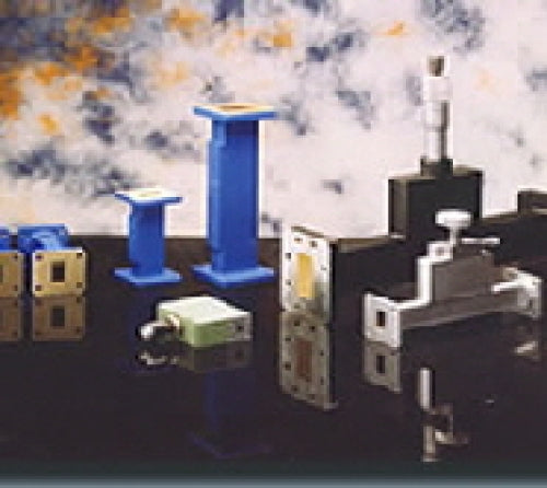
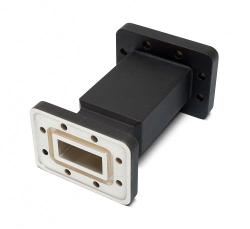
We offer a range of Low Power and Sliding load terminations has been designed to offer optimum Return Loss Performance. Sliding loads The standard sliding loads are assembled in the... Read full description
SKU: loads
Categories: Waveguides
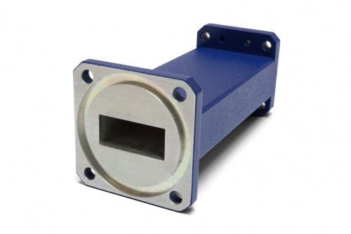
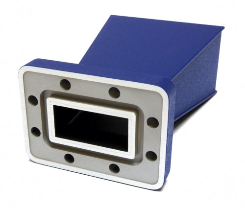
We offer a range of Low Power and Sliding load terminations has been designed to offer optimum Return Loss Performance.

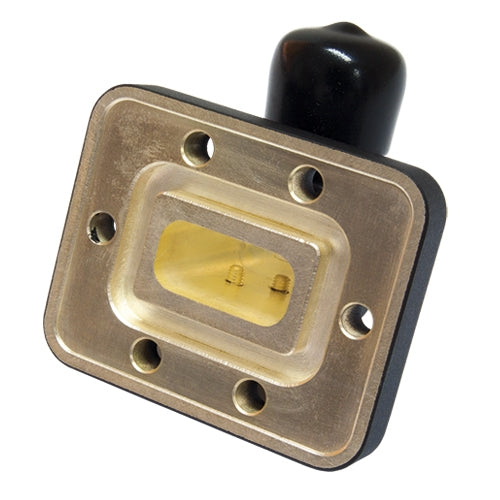
The standard sliding loads are assembled in the same way as the standard fixed loads using selected waveguide tube and precise positioning of the flange interface. Operation of the sliding element is by a push/pull mechanism and a locking screw is provided for repetitive measurements.
Specification:
V.S.W.R: See table (based on spot frequency operation)
Material: Brass
Load material: Iron loaded resin
Finish: Blue paint

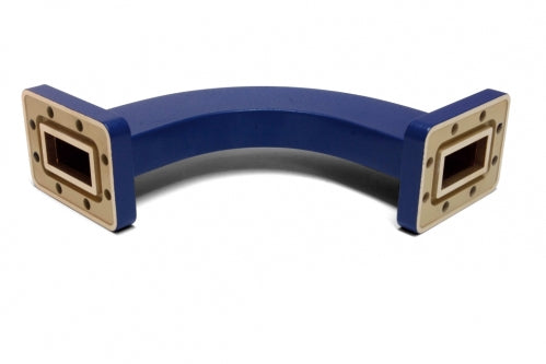
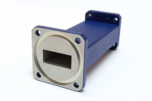
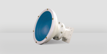
The waveguide loads devices are manufactured from selected waveguide tube. The flange interface is precisely controlled to offer the optimum performance.
Specification:
Material: Brass
Load material: Iron loaded resin
Finish: Blue paint
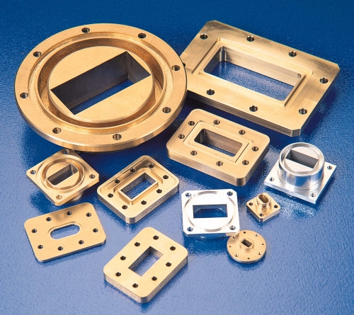
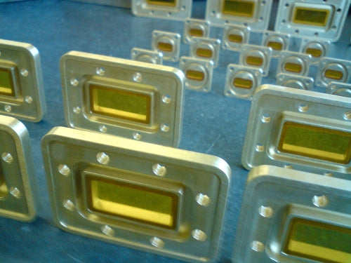
Calibration quality fixed loads
Specification:
Material: Aluminium
Load material: Iron loaded resin
Finish: Blue paint, iridited flanges
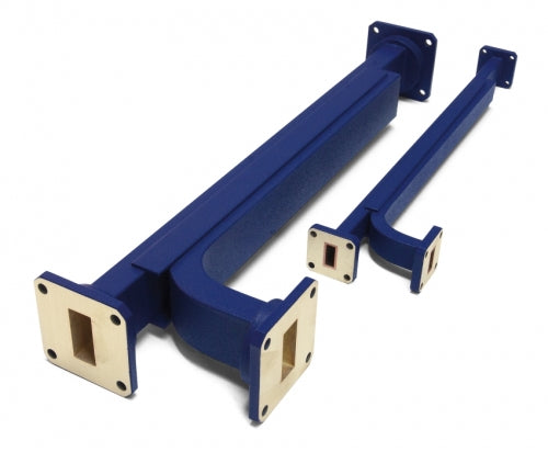
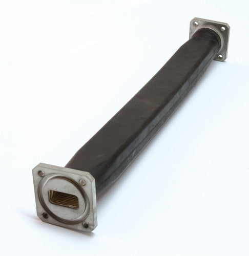
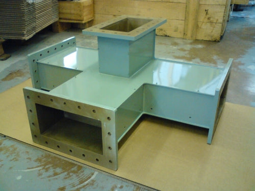
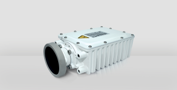
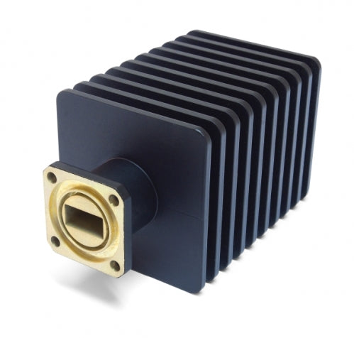
High and medium power loads are based on silicon carbide elements for optimum thermal efficiency. Several sizes of loads per waveguide size may be available depending on the power requirement.
The range of high power waveguide loads is continually being expanded. The power rating depends on the waveguide size, ambient temperatures and the fin area available, (e.g. the two WG17 loads shown below have power ratings of 800W and 500W and the WG10 load 2000W), but for very high power requirements, either multiple load elements and internal power splitters or a custom load element is designed in house for optimum heat distribution. Special designs are available for requirements with extremely high peak powers.
All load elements are made from silicon carbide which is thermally bonded to the heatsink and have a match better than 1.1:1.


The majority of loads have optimum heat dissipation when mounted horizontally, but fin arrangements are also available for vertical mounting - if necessary (at extra cost). Please consult the factory for higher power ratings and support bracketry.
Load sizes vary enormously depending on power dissipation and if forced air or convection is used - but as a very rough guide, the approximate size of a 1kW load using convection would be 220 x 220 x 300mm and a 2kW load 255 x 255 x 550mm
Designs are available for waveguide sizes WG10 to WG22 in various power ratings. Please contact the factory with the waveguide size, power dissipation and frequency range needed (it is often possible to optimise performance over a particular frequency range when very high power loads are needed).
Example: FL 16 S Q Z 402 B
For more details and prices please use the product enquiry form or contact our sales team.
Download the Loads (1.5kW to 3kW, Convection and Watercooled) specifications.
Add your details below to find out more about this product. We'll aim to get back to within 48 working hours.